-
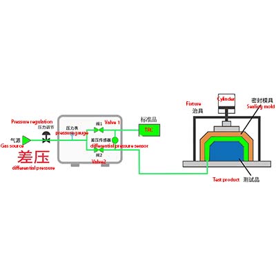
 Differential Pressure Method: By comparing good and
defective products, the seal integrity is
determined.
-
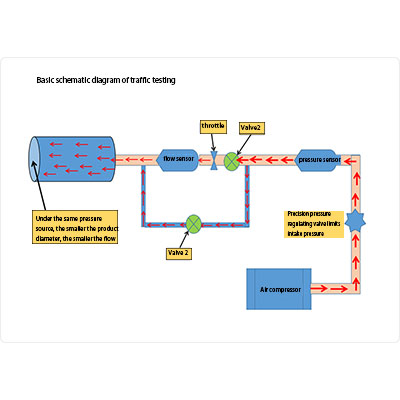
 Flow Method: Determines seal integrity by measuring
the flow rate of leaking gas.
-
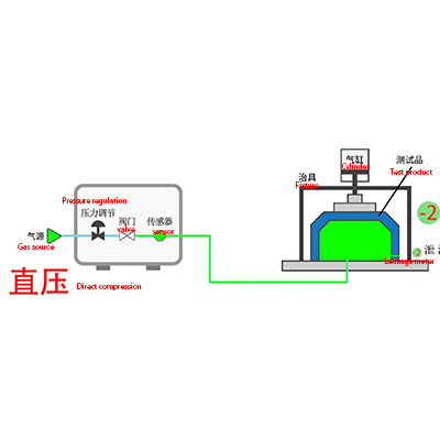
 Direct Pressure Method: Detects leakage by monitoring
pressure changes inside the sealed object—commonly by
blowing or sucking air to observe the change and
determine if there is a leak.
Our air leak testers are suitable for airtightness testing of various types of products, especially in industries such as electronics, medical devices, and automotive components. The specific testing range can be customized based on the material and structure of the product.
Our air leak testers have undergone rigorous environmental testing and can operate stably under varying temperature and humidity conditions. For special environmental requirements, we also provide customized solutions.
Our equipment uses high-precision sensors to ensure the accuracy of test results. Depending on the model, it can detect extremely small gas leaks, meeting the requirements of various application scenarios.
Possible causes:
1. Temperature changes: Temperature fluctuations in the testing environment or the product being tested can cause gas to expand or contract, affecting pressure readings and potentially resulting in negative leakage values.
2. Product or fixture deformation: The product may deform during the pressurization process, changing the internal volume and causing pressure changes, which can lead to negative values.
Solutions:
1. Temperature control: Maintain a stable temperature for both the testing environment and the product to prevent pressure changes caused by temperature differences.
2. Equipment inspection: Regularly check fixtures and pipelines to ensure there is no deformation or damage, keeping the testing volume stable.
Possible Causes:
1. Inconsistent operation: Different operators may use inconsistent methods, leading to varying test results.
2. Environmental factors: Changes in temperature, humidity, etc., can affect the stability of test results.
3. Equipment calibration issues: If the equipment is not calibrated regularly or calibrated improperly, measurement accuracy may decrease.
Solutions:
1. Standardize operating procedures: Develop detailed operating procedures and train operators to ensure consistent methods.
2. Control environmental conditions: Conduct tests in environments where temperature, humidity, and other factors are controlled to minimize external interference.
3. Regular equipment calibration: Calibrate the equipment according to the manufacturer's recommended schedule to ensure measurement accuracy and stability.
Possible Causes:
1. Power issues: Loose power connections or a faulty power module may prevent the equipment from starting. BILIBILI.COM
2. Hardware failure: Failure of critical components such as sensors or controllers can affect the equipment startup.
Solutions:
1. Power check: Ensure that the power connection is secure, the power cable is undamaged, and the power module is functioning properly.
2. Component check: Inspect the working condition of key components, and if necessary, contact the manufacturer for repairs or replacements.
We offer comprehensive pre-sales and after-sales support, including equipment operation training, on-site commissioning, and technical assistance. Our team of engineers can provide one-on-one technical consulting to ensure you can quickly get started and use the equipment efficiently.
Our air leak testers are designed with ease of maintenance in mind. Routine use only requires basic cleaning and calibration. We also offer regular maintenance services to ensure long-term stable operation of the equipment.
Possible Causes:
- Loose connections: Loose piping connections or damaged seals may cause gas leakage.
Solutions:
- Connection check: Ensure all piping connections are tight with no looseness or leakage.
- Seal inspection: Regularly check the integrity of seals and replace them promptly if damaged.
Possible Cause:
Display screen damage: External impact or prolonged use may cause the display screen to malfunction.
Solution:
Display screen check: Inspect the display screen for any damage. If necessary, contact the manufacturer for repair or replacement.
To ensure the accuracy of the instrument's measurements, regular calibration is essential. We offer regular calibration services for the equipment, which can be done on-site or at our factory, based on customer needs. The equipment manual also provides simple self-calibration instructions for customers to perform on their own.
1. Possible Causes
1. Issues with the Leak Testing Device
Insufficient sensor accuracy: Aging of pressure or flow sensors can cause fluctuation in measurement data.
Fluctuating air source pressure: Instability in the pressure from the air pump or source (e.g., pressure fluctuation, insufficient supply) directly affects the repeatability of the inflation or vacuum process.
Inconsistent valve response: Differences in the switching times of solenoid or control valves can cause deviations in inflation/exhaust times or pressure control.
2. Changes in Testing Conditions
Environmental temperature/humidity fluctuations: Changes in temperature can cause gas volume to expand or contract, and humidity changes may affect gas density or resistance in leak paths.
Defects in the sealing fixture: Gaps or uneven pressure on the contact surfaces of the workpiece and fixture, such as looseness or deformation.
Defects in the workpiece itself: Material deformation, residual liquid, or foreign objects (e.g., debris, oil) can cause temporary leakage changes.
3. Human Operation Factors
Insufficient or inconsistent force applied to the leak testing fixture.
Non-standard testing procedures (e.g., inconsistent inflation time, testing started before system stabilization).
2. Solutions
1. Device Optimization
Regular calibration and maintenance: Calibrate sensors (e.g., pressure sensors, flow meters) on schedule and replace aging components (e.g., seals, valves).
Hardware upgrade: Use more accurate sensors and faster-response valves (e.g., piezoelectric valves).
Improve air source stability: Install pressure regulators, air tanks, or use high-precision air pumps to ensure stable supply pressure.
2. Control Testing Environment
Constant temperature and humidity environment: Place the testing area in an environment with controlled temperature and humidity, or use software algorithms to compensate for the effects of temperature/humidity (e.g., dynamically correcting leakage rate based on ideal gas equations).
Workpiece pre-treatment: Clean the workpiece surface to ensure no oil, debris, or foreign objects, and standardize clamping procedures (e.g., using pneumatic fixtures or torque wrenches to ensure consistent clamping force).
3. Standardize Operation Procedures
Standardized operation manual: Define parameters such as inflation time, balancing time, and testing cycle to avoid arbitrary adjustments.
Automation replacing manual operations: Use robots or automated fixtures to ensure consistent workpiece clamping and testing processes.
I. Possible Causes
1. Sensor Nonlinear Response
Range Limit of the Detector: Pressure sensors typically have a limited linear range. At high pressures (e.g., >500kPa), the sensor may exceed its optimal operating range, leading to nonlinear error where the output signal diverges from the pressure value.
Temperature Drift: At high pressure, the sensor generates more heat, which, without adequate temperature compensation, may cause zero drift or sensitivity changes. This is particularly noticeable in designs without temperature regulation.
2. Sealing and Leakage Issues
Sealing Material Deformation: Under high pressure, sealing elements (e.g., O-rings) may be excessively compressed, causing permanent deformation or micro-leaks, particularly in low-hardness materials (e.g., silicone) that lack sufficient rebound under high pressure.
Structural Deformation: Detection chambers or pipes may experience slight elastic deformation (e.g., metal expansion) under high pressure, leading to volume changes that affect the accuracy of pressure decay calculations.
3. Gas Source Stability and Response Speed
Insufficient Pump Pressure Supply: At high pressures, the pump must maintain stable gas supply. If the pump lacks sufficient power or the air circuit is poorly designed (e.g., small pipe diameter), it can cause extended pressurization times or pressure fluctuations.
Valve Response Delay: At high pressure, the pump must maintain stable gas supply. If the pump power is inadequate or the air circuit is poorly designed (e.g., small pipe diameter), it can cause extended pressurization times or pressure fluctuations.
4. Changes in Gas Physical Properties
Impact of Gas Compressibility: At high pressures, the gas deviates from the ideal gas law (requiring correction with the Van der Waals equation), causing a larger deviation between the theoretical and actual pressure-volume relationships.
Adiabatic Effects: During rapid pressurization, the gas temperature rises (adiabatic compression), and during the test, the temperature gradually drops, causing transient interference in the pressure decay curve.
II. Solutions
1. Hardware Optimization
Select High-Precision Sensors: Use sensors with a range covering high-pressure segments (e.g., 0-1MPa) and linear error ≤ 0.1% FS, and integrate temperature compensation modules (e.g., PT100 temperature sensors).
Enhance Sealing Design: Use high-pressure-specific sealing materials (e.g., fluororubber or polyurethane) or employ metal sealing structures (e.g., conical seals); add redundant sealing rings for safety.
Anti-Deformation Structural Design: Use thick-walled metal (e.g., stainless steel 316L) for the detection chamber and conduct finite element analysis (FEA) to verify deformation, or compensate for volume changes through calibration.
2. Improvements to Gas Circuit and Control System
Dynamic Temperature Compensation: Real-time temperature data collection to correct the temperature term in the gas state equation (e.g., using the Clapeyron equation).
Pressure Decay Model Optimization: Develop nonlinear leakage models for high-pressure gases (e.g., exponential decay fitting) to replace traditional linear approximation algorithms.
3. Standardization of Testing Processes
Extend Balance Time: Determine the thermal equilibrium time at high pressure through experiments (e.g., 30 seconds at 500kPa) and enforce waiting time in the program.
Segmented Testing Strategy: Apply different testing parameters (e.g., sampling frequency, leakage rate threshold) for high-pressure (>500kPa) and low-pressure segments to improve targeting.
With the rapid development of the new energy industry, materials such as lithium-ion batteries, fuel cells, and solar cells are facing increasingly stringent sealing performance requirements. Against this backdrop, whether traditional testing methods can still meet the sealing testing needs of new energy materials has become a focal point in the industry. This article will focus on analyzing the key role of gas leak detectors in the sealing performance testing of new energy materials.
Limitations of Traditional Testing Methods
Traditional sealing detection methods mainly include visual inspection, water immersion testing, etc. These methods perform well in conventional material testing, but the advantages of gas leak detectors become especially apparent when dealing with extreme working conditions of new energy materials:
- Poor temperature adaptability: Most traditional sealing detection devices cannot maintain test accuracy across a wide temperature range.
- Insufficient simulation of high-pressure environments: Difficult to simulate the sealing performance under high-pressure conditions for new energy batteries.
- Poor sensitivity to microleaks: Traditional methods lack sensitivity in detecting tiny leaks.
The Key Role of Gas Leak Detectors
Among various sealing detection needs, modern gas leak detectors provide more precise solutions. New energy materials such as battery separators and fuel cell proton exchange membranes, whose sealing performance directly affects product safety and lifespan.
Technological Advantages of Modern Gas Leak Detectors
- High-precision sealing detection: Using differential pressure or mass flow methods, with a detection accuracy of 0.1Pa.
- Wide-range environmental simulation: Sealing performance testing under different temperature and pressure conditions.
- Non-destructive sealing detection: Measures while maintaining the material’s original state.
- Dynamic monitoring capabilities: Real-time monitoring of the evolution of sealing performance as conditions change.
Application Case Analysis
Taking lithium-ion batteries as an example, a gas leak detector can precisely measure:
- Shell sealing performance (IP67/IP68 level verification).
- Electrode terminal sealing reliability.
- Explosion-proof valve opening pressure.
- Sealing degradation rate after long-term use.
Traditional sealing detection methods require multiple devices for separate testing, while modern gas leak detectors can perform all sealing performance tests in a one-stop solution.
Future Development Trends
To meet the growing sealing testing needs of new energy materials, gas leak detector technology will develop in the following directions:
- Multi-parameter integrated detection: Integrating multiple parameters such as sealing performance and pressure resistance for simultaneous measurement.
- Smart sealing detection systems: Establishing sealing performance prediction models based on AI algorithms.
- Standardized testing procedures: Promoting the standardization and unification of sealing detection in the new energy industry.
-
 Differential Pressure Method: By comparing good and
defective products, the seal integrity is
determined.
-
 Flow Method: Determines seal integrity by measuring
the flow rate of leaking gas.
-
 Direct Pressure Method: Detects leakage by monitoring
pressure changes inside the sealed object—commonly by
blowing or sucking air to observe the change and
determine if there is a leak.
Our air leak testers are suitable for airtightness testing of various types of products, especially in industries such as electronics, medical devices, and automotive components. The specific testing range can be customized based on the material and structure of the product.
Our air leak testers have undergone rigorous environmental testing and can operate stably under varying temperature and humidity conditions. For special environmental requirements, we also provide customized solutions.
Our equipment uses high-precision sensors to ensure the accuracy of test results. Depending on the model, it can detect extremely small gas leaks, meeting the requirements of various application scenarios.
Possible causes:
1. Temperature changes: Temperature fluctuations in the testing environment or the product being tested can cause gas to expand or contract, affecting pressure readings and potentially resulting in negative leakage values.
2. Product or fixture deformation: The product may deform during the pressurization process, changing the internal volume and causing pressure changes, which can lead to negative values.
Solutions:
1. Temperature control: Maintain a stable temperature for both the testing environment and the product to prevent pressure changes caused by temperature differences.
2. Equipment inspection: Regularly check fixtures and pipelines to ensure there is no deformation or damage, keeping the testing volume stable.
Possible Causes:
1. Inconsistent operation: Different operators may use inconsistent methods, leading to varying test results.
2. Environmental factors: Changes in temperature, humidity, etc., can affect the stability of test results.
3. Equipment calibration issues: If the equipment is not calibrated regularly or calibrated improperly, measurement accuracy may decrease.
Solutions:
1. Standardize operating procedures: Develop detailed operating procedures and train operators to ensure consistent methods.
2. Control environmental conditions: Conduct tests in environments where temperature, humidity, and other factors are controlled to minimize external interference.
3. Regular equipment calibration: Calibrate the equipment according to the manufacturer's recommended schedule to ensure measurement accuracy and stability.
Possible Causes:
1. Power issues: Loose power connections or a faulty power module may prevent the equipment from starting. BILIBILI.COM
2. Hardware failure: Failure of critical components such as sensors or controllers can affect the equipment startup.
Solutions:
1. Power check: Ensure that the power connection is secure, the power cable is undamaged, and the power module is functioning properly.
2. Component check: Inspect the working condition of key components, and if necessary, contact the manufacturer for repairs or replacements.
Possible Causes:
1. Temperature Changes: Temperature fluctuations in the testing environment or the tested product can cause gas to expand or contract, affecting pressure readings and potentially resulting in negative leakage values.
2. Deformation of the Product or Fixture: The product may deform during the pressurization process, changing the internal volume and causing pressure variations, leading to negative values.
Solutions:
1. Temperature Control: Maintain a stable temperature in the testing environment and for the product to avoid pressure changes caused by temperature differences.
2. Equipment Inspection: Regularly inspect fixtures and pipelines to ensure there is no deformation or damage, maintaining stable test volumes.
Possible Causes:
1. Inconsistent Operation: Differences in the operation methods of different operators may lead to variations in test results.
2. Environmental Factors: Changes in temperature, humidity, and other environmental factors can affect the stability of the test results.
3. Calibration Issues: If the equipment has not been calibrated regularly or is improperly calibrated, it can lead to reduced measurement accuracy.
Solutions:
1. Standardize Operations: Establish detailed operating procedures and train operators to ensure consistent methods of operation.
2. Control Environmental Conditions: Conduct tests in environments where temperature and humidity are controlled to minimize interference from external factors.
3. Regular Equipment Calibration: Calibrate the equipment at the intervals recommended by the manufacturer to ensure measurement accuracy and stability.
Possible Causes:
1. Power Issues: Loose power connections or a faulty power module may prevent the equipment from starting. BILIBILI.COM
2. Hardware Failure: Failures in critical components like sensors or controllers can affect the equipment’s startup.
Solutions:
1. Power Inspection: Ensure the power connection is secure, the power cable is undamaged, and the power module is functioning properly.
2. Component Inspection: Check the working condition of critical components and contact the manufacturer for repairs or replacements if necessary.
Possible Causes:
- Loose Connections: Loose tubing connections or damaged seals may cause gas leakage.
Solutions:
- Connection Inspection: Ensure all tubing connections are tightened and free from looseness or leakage.
- Seal Inspection: Regularly check the integrity of seals and replace them if any damage is found.
Possible Cause:
Display Screen Damage: External impact or prolonged use may cause the display screen to malfunction.
Solution:
Display Screen Inspection: Check the display screen for any damage, and if necessary, contact the manufacturer for repairs or replacement.
To ensure the accuracy of the instrument, regular calibration is necessary. We offer periodic calibration services for the equipment, either on-site or at the factory, according to customer needs. The equipment manual also provides simple self-calibration instructions for customers to operate on their own.